Case Study – Gas-Turbine Combustor CFD Model
The challenge
A gas-turbine manufacturer builds land gas-turbines fuelled by natural gas. The
manufacturer must convince the operator that the flame in the combustion chambers
of the gas-turbine will remain stable at all operating conditions, with no risk of
flash-back and damage to the engine.
The solution
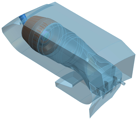
The gas-turbine is equipped with sixteen combustion chambers arranged at 22.5°
intervals inside an annular casing. Atkinson Science used state-of-the-art
computational fluid dynamics (CFD) software to create a CFD model consisting of a
single combustion chamber and a 22.5° sector of the annular casing, plus a
section of the nozzle guide vane assembly downstream of the combustion chamber.
The NGV assembly was scaled to give an integer number of vanes downstream of the
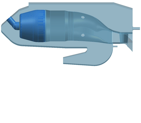
chamber. Figures 1 and 2 show isometric and side views of the CFD model.
Figure 1 Isometric view of the CFD model
|
|
Figure 2 Side view of the CFD model
|
|
|
|
The CFD model has three inflows and three outflows. The three inflows consist of
the air supply at the outlet from the compressor, the main fuel supply and the
pilot fuel supply. All three flows were specified in terms of total temperature
and total pressure. The three outflows consist of the flow of hot combustion gases
at the outlet from the nozzle guide vanes and two bleed flows from the annular
casing. The flow from the NGVs was specified in terms of the static pressure. This
static pressure was determined from a separate computation of the flow through the
NGVs based on the measured total temperature and total pressure of the flow
leaving the combustion chamber and the measured mass flow. If the static pressure
is specified correctly then the flow through the NGVs should choke at the measured
mass flow. The bleed flows were given their measured values.
The combustion chamber is an example of dry, low emissions (DLE) combustor
technology in which the mixture of fuel and air is intentionally lean to prevent
NOx emissions. The air supply and the main fuel supply are passed through swirl
vanes before they enter the chamber. The swirl causes a back-flow along the
centreline of the chamber which keeps the mixture alight. We specified total
conditions at all inlets. Consequently, any variations in static pressure in the
combustion chamber will cause the flows of fuel and air to fluctuate and may
create an instability that is characteristic of DLE combustors.
The turbulence in the flow was modelled with the differential stress model of
Ref. [1]. The k-ε model, which is a possible alternative, has a
tendency to produce too much turbulence in swirling flows and might inhibit any
natural instability. The combustion of natural gas and air was modelled with the
laminar flamelets model of Ref. [2] in conjunction with a reaction progress
variable. The progress variable predicts the degree to which the mixture has burnt
and indicates the position of the flame front which separates burnt mixture from
unburnt mixture. This combination of turbulence model and combustion model has
been used many times before to compute lean premixed flames and is known to give
accurate predictions of flame speed – see, for example, Refs. [3] to [6].
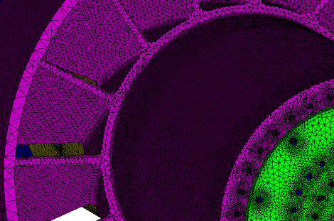
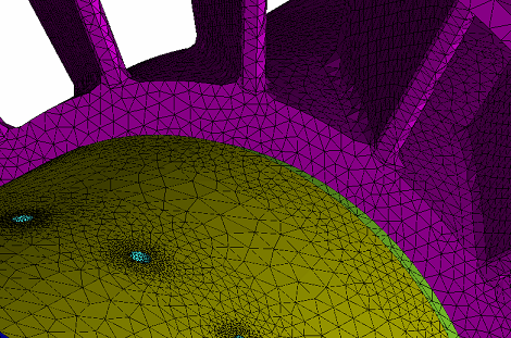
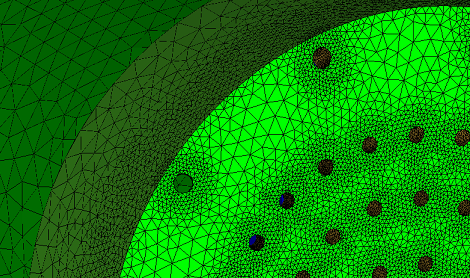
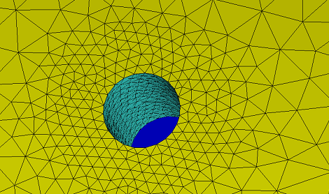
The CFD model contained a total of 8.8 million mesh elements – enough to
resolve the flow features in every part of the model. Each fuel hole and air hole
was meshed individually to ensure that the profile of velocity was resolved
properly. Figures 3 to 6 give an indication of the density of the meshing in the
CFD model.
Figure 3 Fuel injector and swirler
|
|
Figure 4 Main fuel holes and swirler
|
|
|
|
|
|
|
Figure 5 Fuel injector end face
|
|
Figure 6 Main fuel hole
|
|
|
|
We simulated the flow and combustion in the combustion chamber time-accurately at
ten operating points: full power, 70% power and 50% power at air inlet
temperatures of 228 K, 288 K and 318 K, plus idling at 288 K. The time-step size
was 0.05 milliseconds – small enough to resolve any flow or combustion
transients – and the total number of time steps was 250 for a total
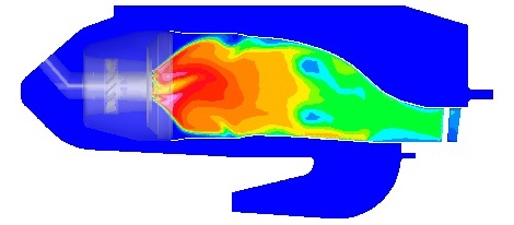
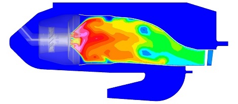
simulation time of 12.5 milliseconds. From the results of each computation we
created a movie of the flame based on the temperature in the combustion chamber.
Figures 7 and 8 show snapshots after 7.5 and 12.5 milliseconds from the movie
for the full power, 288 K condition. The outer edge of the flame at the combustion
chamber wall appears wrinkled because the flame flickers like a real flame.
However, the flame front – the interface between the cool unburnt mixture
and the hot burnt mixture – remains fixed. Over the course of the movie
there was no sign of an instability that might lead to flash-back and damage to
the combustion chamber. We created movies for the other nine conditions, but we
could not discern an instability mechanism in any of them. We were led to the
conclusion that the combustion chamber was, in fact, well-designed with a very
stable flame at all of the operating points considered.
Figure 7 Temperature after 7.5 ms
|
|
Figure 8 Temperature after 12.5 ms
|
|
|
|
The benefits
With assistance from Atkinson Science, the gas turbine manufacturer was able to
demonstrate to the operator that the engine was free from the risk of combustion
instability at the operating conditions considered. Our movies of the flame had
the characteristics of a real flame, but we could find no sign of an instability
mechanism that might lead to flash-back and damage to the combustion chamber.
References
- C. G. Speziale, S. Sarkar and T. B. Gatski, "Modeling the
pressure-strain correlation of turbulence: an invariant dynamical systems
approach," Journal of Fluid Mechanics, Vol. 227, pp. 245-272, 1991.
- N. Peters, "Laminar diffusion flamelet models in non-premixed
combustion," Progress in Energy and Combustion Science, Vol. 10, pp. 319-339,
1984.
- F. Biagioli, "Stabilization mechanism of turbulent premixed flames
in strongly swirling flows," Combustion Theory and Modelling, Vol. 10,
pp. 389-412, 2006.
- W. Polifke, P. Flohr and M. Brandt, "Modelling of inhomogeneously
premixed combustion with an extended TFC model," Journal of Engineering for
Gas Turbines and Power, Vol. 124, pp. 58-65, 2002.
- F. Biagioli, V. L. Zimont and K. J. Syed, "Modelling and simulation
of gas combustion in DLE burners based on a turbulent flame closure approach,"
Proceedings of the International Joint Power Generation Conference and
Exposition, New Orleans, Louisiana, USA, 4-7 June 2001.
- V. L. Zimont, W. Polifke, M. Bettelini and W. Weisenstein,
"An efficient computational model for premixed turbulent combustion at high
Reynolds numbers based on a turbulent flame speed closure," Journal of
Engineering for Gas Turbines and Power, Vol. 120, pp. 526-532, 1998.
Acknowledgement
Atkinson Science acknowledges the contributions of G-J. Sims and J. P. Wood to
this work.