Case Study – Engine Intake of a Hypersonic Air Vehicle
The challenge
Aeronautical engineers are designing an unmanned hypersonic vehicle to fly at
Mach 10 at an altitude of 45 km. The aircraft will be powered by an air-breathing
engine (a supersonic-combustion ramjet). Combustion efficiency dictates that the
speed and temperature of the air entering the combustion chamber of the engine
must not be more than Mach 3.5 and 1800 K, respectively. The engineers must design
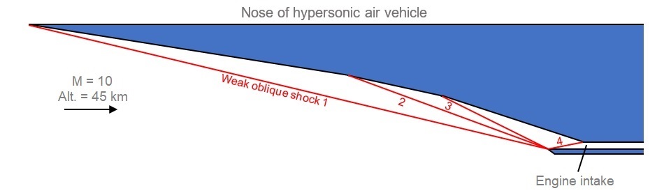
the underside of the nose of the aircraft to create a series of weak oblique
shocks ahead of and inside the engine intake so that the air entering the
combustion chamber meets these requirements.
The solution
An oblique shock is formed when air flowing over a surface at supersonic speed
encounters a sudden change in surface direction. Across the shock there is a fall
in Mach number and a rise in temperature and pressure. To create a series of
oblique shocks, the underside of the nose of the aircraft must be made of a series
of flat panels at increasing angles to the flight direction. The angle and length
of each panel must be designed so that the oblique shocks resulting from each
change of flow direction all terminate at the lip of the engine intake.
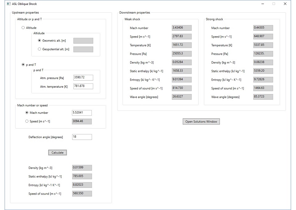
Atkinson Science created a Windows application to calculate the wave angle of an
oblique shock and the change in properties across the shock. The application is
based on classical theory which assumes that the flow upstream and downstream of
the shock is isentropic. We specified three panels along the underside of the nose
of the aircraft with angles of 9°, 13° and 18° to the flight direction. The
Windows application gave the wave angle of the shock at the leading edge of each
panel and it was only necessary to adjust the length of each panel to make the
three shocks terminate at the lip of the engine intake. A fourth oblique shock was
formed inside the intake. Across the four shocks the Mach number fell from 10 to
6.9 to 6.2 to 5.5 to 3.4 and the temperature rose from 264 to 517 to 628 to 782 to
1652 K. In the illustration below the Windows application displays the change in
flow properties across the fourth shock. The flow between the shocks is assumed to
be isentropic, so the method does not account for the losses or the displacement
of the flow due to the boundary layer on the underside of the nose. However, it
provides good first approximations to the lengths of the panels and the overall
size and shape of the nose.
The benefits
Atkinson Science quickly established the basic design of the nose of the
hypersonic vehicle by incorporating classical shock theory into a Windows
application.
Try our free-to-use
web version of the Oblique Shock Windows application.