Case Study – Fume Dispersion from the Institute of Biomedical Research
The challenge
The Institute of Biomedical Research (IBR) is responsible for 20-30% of the
research carried out by the University of Birmingham. The IBR is a six-storey
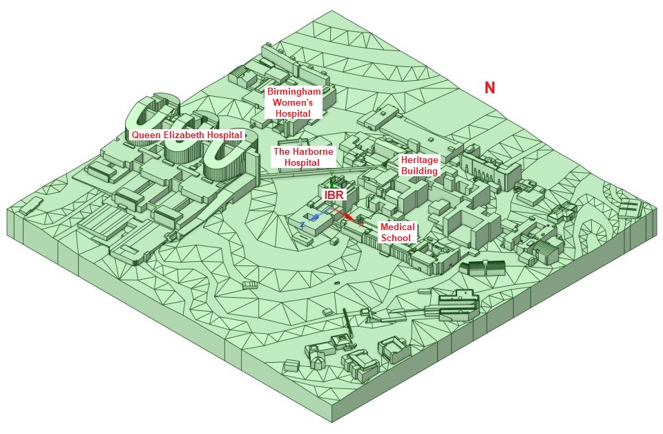
building located in the northwest corner of the Edgbaston Campus. Figure 1 shows a
model of the IBR and the surrounding buildings. The IBR has a flat roof and
several roof-top flues that discharge pollutants to the atmosphere. At the moment,
there is a restriction in place that requires the flues to be shut down when
maintenance workers need access to the roof. The disruption that this restriction
causes to the research activities is considerable.
Buildings with flat roofs often have recirculations on their roofs caused by the
wind separating off the sides of the building. There is a risk that pollutants may
be driven down to the roof, unless the outlets from the flues are well above the
recirculations. The Estates Office asked Atkinson Science to propose a programme
of CFD simulations to show whether the flues are tall enough to prevent pollutants
becoming trapped in the recirculations causing a health hazard to workers on the
roof and consequently whether or not the restriction can be lifted.
Fig 1 Model of the IBR and surrounding
buildings
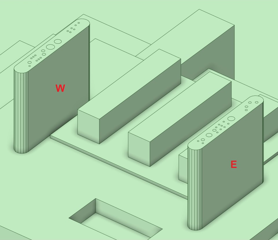
The flues are arranged in two lines running north to south on the west and east
sides of the roof, as shown in Figure 2. A cladding runs all the way around the
flues to hide them from sight. The discharges from the flues are room air
containing a trace concentration of a pollutant originating in a fume cupboard or
safety cabinet. The concentration of the pollutant leaving the flue will be below
the long-term exposure limit. The discharges do not normally pose a safety hazard.
However, a safety hazard can occur if a cleaning fluid or other substance is spilt
accidentally in a fume cupboard or safety cabinet. Then a ten or even a
hundred-fold increase in the concentration of pollutant leaving the flue can
occur.
There is no regulation for the number of dilutions a pollutant from a flue must
undergo before it comes into contact with humans. However, we would expect a
well-designed system of flues to produce at least 100 dilutions before pollutants
reach anyone on the roof. This amount of dilution would be enough to guard against
a spill or other accident in a fume cupboard or safety cabinet.
Fig 2 Roof-top flues
The solution
Atkinson Science created a CFD model of the IBR and the surrounding terrain and
buildings within 300 m of the IBR. We used the model to calculate the dispersion
of the pollutants at three wind speeds (0.25, 2.5 and 10 m s−1) with
the wind from the north and every 45° from the north. For each wind condition, we
plotted the isosurface from each flue representing 100 dilutions of the
pollutants. The isosurfaces from the west flues were coloured blue and the
isosurfaces from the east flues were coloured red.
Figure 3 shows the isosurfaces when the wind is from the north at
10 m s−1. The pollutants do not rise clear of the flues and some
pollutants are caught in the down-flow at the downstream end of the cladding.
Fig 3 Isosurfaces for 100
dilutions. Wind from the north at 10 m s−1
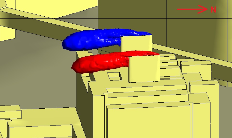
Figure 4 shows the isosurfaces when the wind is from the east at
10 m s−1. The wind is almost normal to the cladding. The cladding turns
the flues into a large bluff body and the pollutants are caught in the down-flow
on the downstream side. The down-flow from the west flues is strong enough to draw
the pollutants down to the roof of the IBR.
Fig 4 Isosurfaces for 100
dilutions. Wind from the east at 10 m s−1
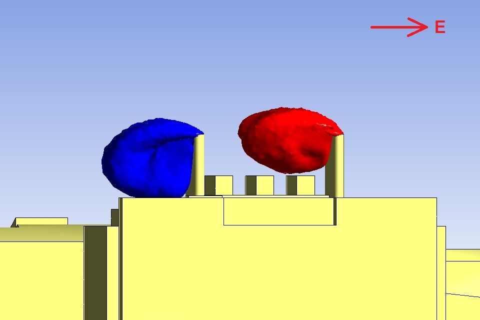
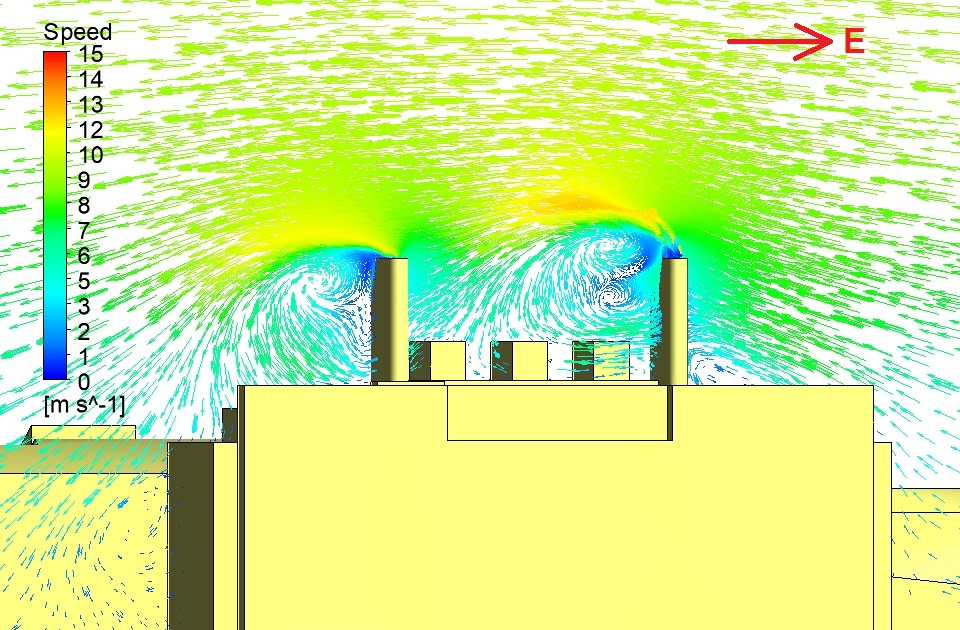
Figure 5 shows the velocity vectors in a vertical plane through the two sets of
flues. The down-flow on the downstream side of the flues can be seen clearly.
Fig 5 Velocity vectors. Wind from the east
at 10 m s−1
The flues were made 8 m tall to enable the pollutants to disperse into the
undisturbed air above the IBR, but when the wind is normal to the cladding at
10 m s−1 the design is rendered ineffective by the cladding, and the
conditions on the roof are not safe for people to work there.
Rather than accept this conclusion, Atkinson Science made some design changes in
the CFD model to see if the problems revealed in the computations could be
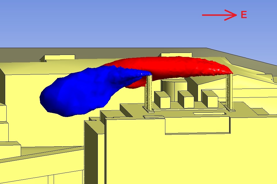
overcome. First, we removed the cladding all together. In Figure 6 the
computation with the wind from the east at 10 m s−1 is repeated, but
with no cladding. The isosurfaces now get clear of the roof.
Fig 6 Isosurfaces for 100 dilutions. Wind
from the east at 10 m s−1. No cladding
In Figure 7 the computation with the wind from the north at 10 m s−1 is
repeated, but with no cladding. There is a tendency for the pollutants
to become trapped in the down-flow behind each flue. The outlet velocities from
the flues are comparatively low at between 3.4 and 10 m s−1
compared with the wind speed. Our second design change was to reduce the diameters
of the flues so that the outlet velocity from all of them was 20 m s−1.
Fig 7 Isosurfaces for 100 dilutions. Wind
from the north at 10 m s−1. No cladding
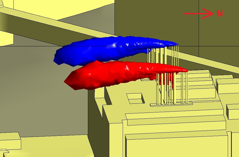
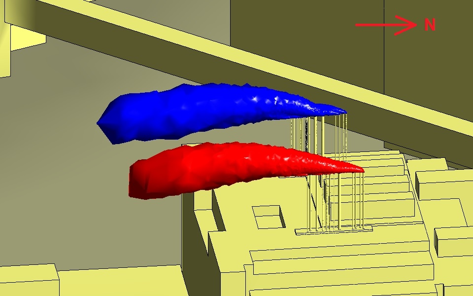
Figure 8 shows the isosurfaces with the wind from the north at 10 m s−1,
but with no cladding and with the outlet velocity from every flue at
20 m s−1. There is now no tendency for the pollutants to accumulate
behind the flues.
Fig 8 Wind from the north at
10 m s−1. No cladding. All flue outlet velocities
20 m s−1
The benefits
The computations showed that with the present design of the flues it is not
possible for people to go on the roof of the IBR when the flues are in operation.
The risk of a spill or other accident in a fume cupboard or safety cabinet makes
this impossible. However, we have shown that some simple design changes offer the
possibility of making the flues safe.