Case Study – Banked Lecture Theatre
The challenge
A new 400-seat banked lecture theatre must provide a temperature of 20 – 23°C for
the occupants for a period of one hour when the theatre is full. A design
consultancy must make a convincing case for a displacement ventilation system
with air supplied through swirl diffusers under the seats and extracted through
extract vents above the stage. The consultancy asked Atkinson Science to create a
CFD model to demonstrate whether or not the ventilation system would meet the
temperature requirement.
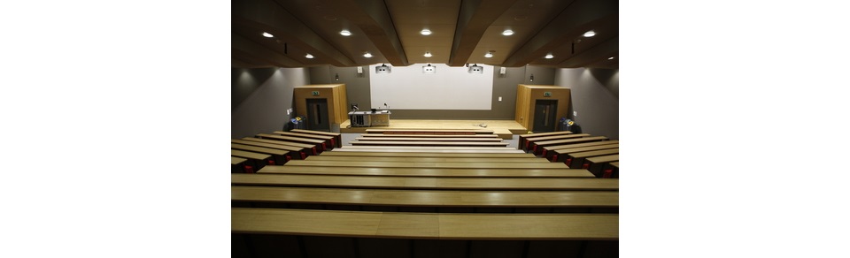
Figure 1 shows a view of the lecture theatre from the back. There are 16 rows of
seats arranged in three groups, with the middle group accounting for about half
the seating area. In the middle group there are either 12 or 13 seats per row,
except in row 16 (the top row) where there are only four seats. There are swirl
diffusers spaced uniformly under the seats in each row.
Fig 1 Banked lecture theatre
The solution
As far as the air conditioning is concerned, the middle group of seats can be
regarded as representative of the lecture theatre as a whole. The temperature
along each row of the middle group will repeat itself from one seat to the next.
Consequently, we need only model a section of the middle group one seat wide to
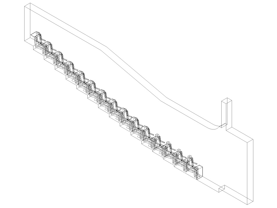
obtain an accurate representation of the temperature in the theatre. Figures 2
and 3 show a side view and an isometric view of the computational domain,
respectively. We must apply periodic boundary conditions to the sides of the
domain to ensure that the temperature on one side of the domain is repeated on the
other. The contribution to the heat load in the middle group of seats made by the
four students in row 16 is only 2.1%, so we omitted these students from the model.
Fig 2 Side view of the computational domain
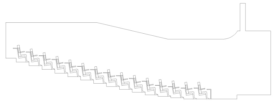
Fig 3 Isometric view of the computational domain
The computed air flow and temperature inside the computational domain can only be
as accurate as the boundary conditions specified at the boundaries of the domain.
The manufacturer’s data sheet for the swirl diffuser gives only a few values of
the axial and radial components of velocity measured half a metre away from the
centre of the diffuser and no measurements of the circumferential velocity
component. The information is not enough to guarantee an accurate CFD model.
Consequently, we created a separate CFD model of the swirl diffuser to generate
the required boundary conditions. The CFD model of the swirl diffuser is described
in the case study Swirl Diffuser CFD Model.
The lecture theatre must provide a comfortable environment for the students from
the moment they fill the theatre to the moment the lecture ends an hour later. The
CFD model was a time-accurate model giving the temperature in the theatre every
ten seconds from the theatre being full to the end of the lecture. At the start of
the simulation the temperature everywhere in the theatre was assumed to be at the
supply temperature of 19°C.
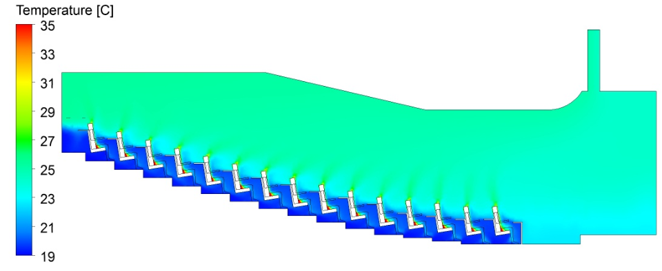
Figures 4 to 6 show the computed temperature in the lecture theatre after one
minute, five minutes and one hour. Over the first minute of the simulation
(Figure 4) we can distinguish individual plumes of warm air rising from the
students and making their way to the extract vents above the stage. After five
minutes (Figure 5) the plumes are barely distinguishable and a two-layer
temperature distribution has developed which is characteristic of displacement
ventilation. The students are enveloped in a layer of cool air while above their
heads warm air makes it way out of the theatre. This temperature formation
persists for the next 55 minutes (Figure 6). The design consultants have
achieved their objective of providing comfortable conditions for the students
over a whole hour.
Fig 4 Computed temperature after 1 minute
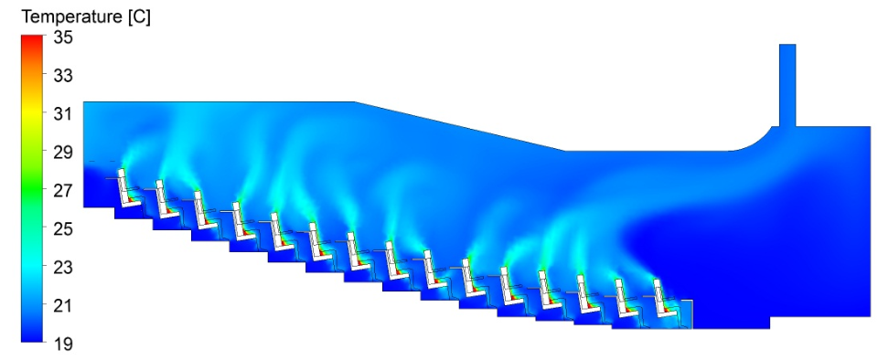
Fig 5 Computed temperature after 5 minutes
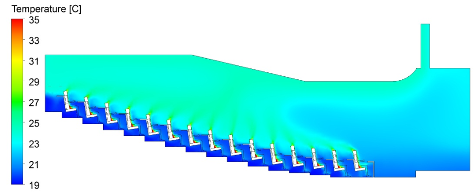
Fig 6 Computed temperature after 1 hour
The benefits
With assistance from Atkinson Science, the design consultants were able to make a
convincing case for their displacement ventilation system. This is just one
example of CFD being used to verify that a ventilation system will perform as
expected when put into operation.