Case Study – Flight Simulator Building
The challenge
A building is being constructed to house a flight simulator similar to the one
shown in Figure 1. The building will be 12 m high and the simulator will be 8 m
tall at its highest point. The air temperature all around the simulator must be
maintained at 18 – 24°C. A design consultancy has devised an air-conditioning
system based on two up-flow computer room air conditioning (CRAC) units. The
consultants must demonstrate that the temperature will remain within the
specification on a hot summer’s day when the outdoor temperature is 29°C and on a
cold winter’s night when the outdoor temperature is −6°C. Apart from the flight
simulator, the building will contain ancillary equipment and up to eight
technicians. In summer the total sensible heat gain will be 71 kW and in winter
the total sensible heat loss will be 27 kW. Each CRAC unit can provide 91 kW of
sensible cooling at an air flow rate of 7.5 m3 s−1. There is
more than enough cooling capacity from one CRAC unit alone to offset the heat gain
in summer and the consultancy intend to operate one unit at 80% of its maximum
flow rate and leave the other unit on stand-by.
Fig 1 Flight simulator

The solution
Atkinson Science created a CFD model of the flight simulator building, as shown in
Figure 2. The CRAC units are labelled CRAC Unit 1 and CRAC Unit 2 in the Figure.
The appropriate fabric heat gain for summer or heat loss for winter was applied to
the outer surface of the model and the relevant heat gains were applied to the
outer surfaces of the flight simulator, ancillary equipment, etc. It is more usual
to have all available CRAC units in operation, but at part-duty, rather than to
have one or more CRAC units standing idle. Consequently, we calculated the
temperature in the building under summer and winter conditions, first with only
CRAC Unit 1 operational, then with only CRAC Unit 2 operational, and finally with
both CRAC units operational. We reduced the air flow rate from each unit to 70% of
the maximum when both units were operational.
Fig 2 CFD model
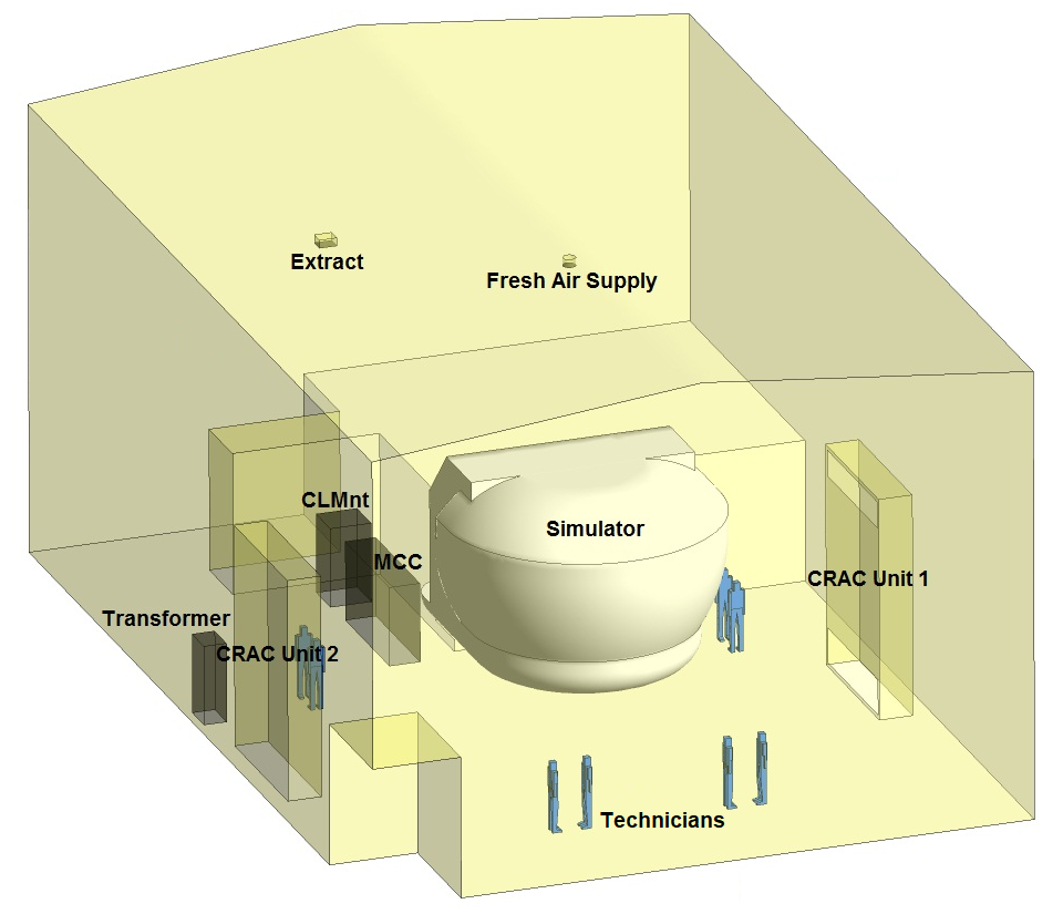
Figure 3 shows the temperature in the building in summer with CRAC Unit 1
operational and CRAC Unit 2 on stand-by. The temperature is stratified as is usual
at the height of summer. Warm air accumulates below the roof but the temperature
is within the specification of 18 – 24°C everywhere else. Unfortunately, the jet
of cool air from the CRAC unit impinges on the flight simulator and is forced to
pass under the simulator causing a temperature drop of 3 – 4°C in the occupied
zone below 2 m that will almost certainly be felt by the technicians. Much the
same happens when the operational CRAC unit is switched from 1 to 2. Having both
CRAC units operational makes the temperature drop all but disappear, as shown in
Figure 4, and the temperature is well within the specification around the flight
simulator.
Fig 3 Temperature for the summer period with CRAC Unit 1 operational
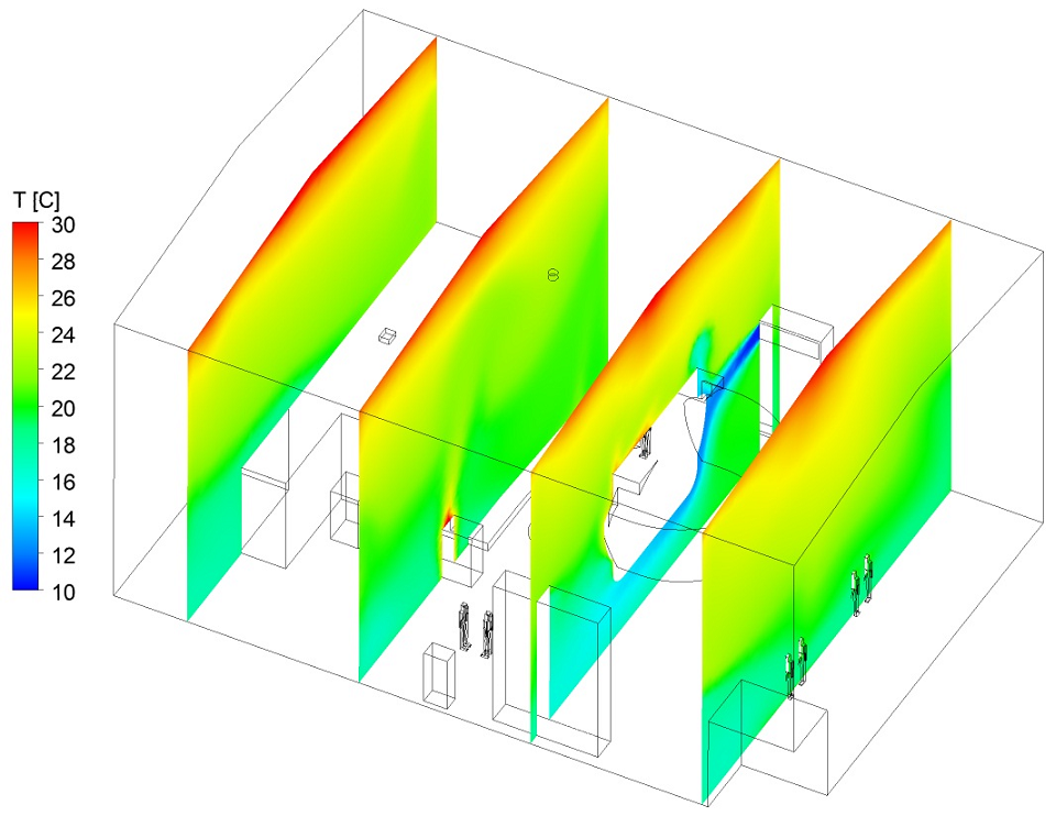
Fig 4 Temperature for the summer period with both CRAC units operational
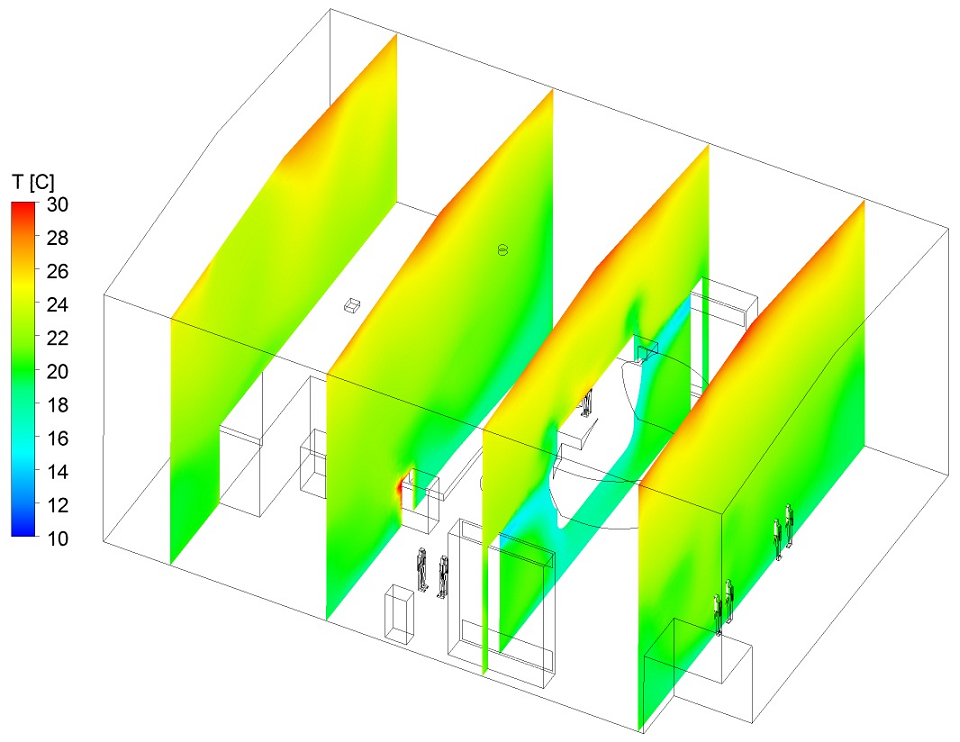
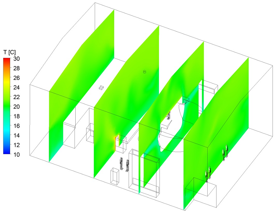
Figure 5 shows the temperature in the building in winter when both CRAC units are
operational. There is now very little stratification because the heat load in the
building is so much lower than in summer. Switching to only one operational CRAC
unit causes differences in temperature of no more than 0.7°C and the temperature
in the occupied zone is essentially uniform whatever configuration is used.
Fig 5 Temperature for the winter period with both CRAC units operational
Having one CRAC unit operational gives perfectly acceptable conditions in winter
but not in summer because this configuration creates a temperature drop in the
occupied zone that will be felt by the technicians. Consequently, our computations
led us to recommend having both CRAC units operational at part-duty. Having only
one unit operational is always likely to produce poorer ventilation because the
unit generates a greater concentration of negatively buoyant air. If the air flow
rate is decreased, for example by adding a filter to the unit, then the air may
slump to the floor and the mixing needed for good ventilation may not occur.
The benefits
Atkinson Science were able to provide the evidence the consultancy needed to show
that its proposed air-conditioning system would meet the temperature specification
when put into practice, but we also recommended a change in the proposed system by
having both CRAC units operational rather than only one operational and the other
on stand-by.